Tutorial - Reverse Engineering
Note
Please see also the beta-release in geWorkbench of the ARACNE algorithm for network reverse engineering. This is a more complete implementation than is present in the Reverse Engineering component.
Outline
In this tutorial, we will cover:
- Background to gene network reverse engineering
- Calculate the mutual information between a hub gene and the others in a dataset
- Calculate the interaction network around the hub gene.
- Display the results in Cytoscape.
- Select a subset of the interaction network (first-neighbors) and save it to a list.
Overview
The primary use of the Reverse Engineering component is to infer regulatory interactions between genes and gene products. The Reverse Engineering component uses the information theory concept of mutual information to find these interactions. Mutual Information is in principle more sensitive and flexible than a simple correlation calculation. It is also invariant under data transformations such as log transformation.
The Reverse Engineering component calculates the information that the expression pattern of one gene carries about the expression of another gene, that is, it is a pairwise calculation. Larger datasets, containing more arrays per marker, will yield greater sensitivity and better statistical support. Full scale runs of reverse engineering algorithms, comparing all markers against each other, and typically done on datasets containing several hundred microarrays, are typically performed on large cluster computers and are not feasible on a desktop machine. During 2006 we hope to provide a remote service that can host such calculations for jobs launched from geWorkbench. However, at present, smaller scale calculations are supported directly in geWorkbench.
As typically used in geWorkbench, the Reverse Engineering component calculates the Mutual Information score between a single hub gene and all other N markers in the dataset. In a second step, a subset containing the best M markers is chosen (with a current limit of 100), and a complete pairwise MxM/2 mutual information calculation is performed between them. The network resulting from this calculation can be displayed as a branched tree of interactions within the Cytoscape component.
Limitations
- The exact algorithm used in Reverse Engineering has not been described in the literature. geWorkbench now also includes a beta-release of the published ARACNE algorithm for network reverse engineering.
- The "Motif Location Histogram" only displays if the "All Arrays" checkbox is checked. This is being fixed.
- The Score vs. Probability graph does not work. This is being fixed.
- There is some overlap in functionality between Profiler tab and the Conditional Analysis tab. Both calculate aspects of conditional interactions.
- There is not yet a tutorial for the Conditional Analysis tab.
- The images shown below were calculated using a slightly larger dataset than is currently being distributed with the tutorials. The images will be updated soon.
Prerequisites
A dataset containing multiple arrays (the more the better) should be loaded into geWorkbench. If data is loaded from separate files, it should be merged into a single microarray datset, either at the time of or after being read in. See the section Projects and Data Files. In this tutorial we will load a dataset also used in other tutorial sections, which has been normalized, and filtered to reduce the number of genes. This file, "webmatrix_quantile_log2_dev1.2_mv0.exp" is available in the tutorial data section. Its derivation is described in Data
Example - Profiler
- Load the data file "webmatrix2_quantile_log2_dev1.2_mv0.exp". This contains a set of 100 experiments on Affymetrix HG_U95Av2 chips. As described above, this file has been quantile normalized, log2 converted, and then filtered to remove markers with a deviation of less than 1.2, in order to reduce the size of the dataset, leaving 2226 markers.
- In the upper right section of geWorkbench find the Reverse Engineering component. It should by default be displaying the Profiler tab.
- In the Markers component search box, on the left side of the geWorkbench interface, enter 1973 and hit enter. This will find the marker 1973_s_at, which is the c-Myc gene, a well-known transcription factor with many interactions. Click on this marker in the list. This will enter the marker into the Hub Gene Label field of the Profiler.

- The default setting in the Profiler is Mutual Information (fast). With this selected, hit Analyze(2D). This will return a list of all markers having a MI score of greater than the cutoff value (the default is 0.2).
- Note - the following images were obtained using a slightly larger dataset, but the results are very similar. New images will be provided soon.

The next step is to create a network. By default, the calculation will be performed for the top 100 scoring genes on list.
- If you wish to use a smaller set of genes, select just those you wish to include from the list by highlighting them.
- By right-clicking and selecting "Add to Set", the selected group will be added to the Markers component as a new set of markers which can be used in other components (sequence retrieval, annotation retriever etc.). If no selection is made, up to the top 100 scoring genes will be added to the new set.
- Hit the Create Network button. The Mutual Information algorithm will be run again on the selected markers, but this time it will include all pairwise combinations of the selected genes, not just each against the hub gene. Each gene is then connected via an edge with the gene it most strongly interacts with, with the chosen hub-gene at the center.
After network creation has been run, an adjacency matrix will be placed in the Projects Folder:

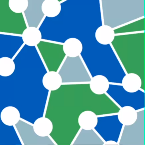
- Select the Cytoscape visualizer if it is not already active. The newly created network will appear similar to that shown here (we have selected the central hub-gene by clicking on it):

A better visualization can be created in Cytoscape by going to the Layout menu, and chosing yFiles->organic. The layout will now appear as:

- Within the network created in Cytoscape, one can select the central gene as already shown above, and then on the Cytoscape menu chose Select->Nodes->First Neighbors of selected nodes.

The first neighbors will be highlighted in the graph,

and also added as a new set in the Markers component.

We can return to the main Reverse Engineering component by clicking on the original dataset in the Project Folders component. If we select the first (highest MI score) marker on the list, the graph shown below is drawn in the Motif Location Histogram display. This shows a plot of the expression values on each array for the selected hub marker vs any other marker selected in the list.
- . The Motif Location Histogram plot is only drawn if you select "All Arrays" or activate a set of arrays in the Arrays/Phenotypes component. If you select "All Arrays", then all the points will be one color:

2. If you activate individual sets of arrays, each set will be drawn in a different color.

Options
Pearson - Uses a Pearson correlation function to calculate the interaction scores.